Brand
:
Robotistan
Product Code
:
13957


Out Of Stock
Notify me when its in stock


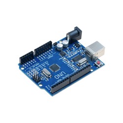
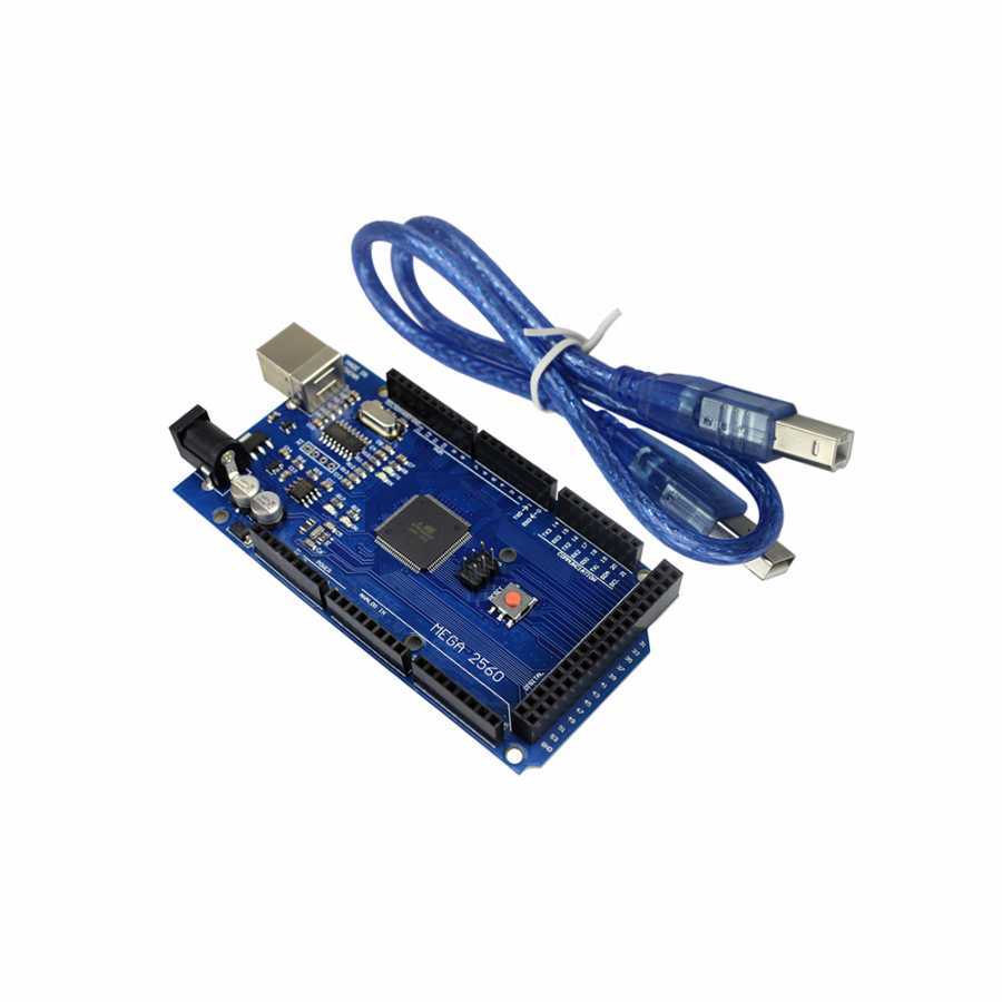
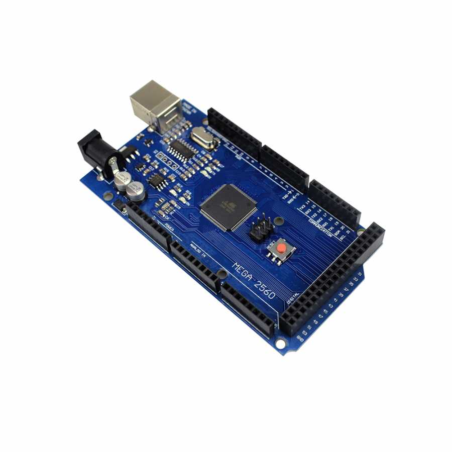
The Mega 2560 R3 development board compatible with Arduino is a development board equipped with the CH340 USB-to-Serial converter and is fully compatible with the Arduino® Mega 2560 R3 design.
Although it has a few minor differences from the original Arduino® Mega, such as the serial converter chip, there are no differences in terms of usage and software.
You can confidently and economically use the Mega 2560 R3 development board in your projects.
The Mega 2560 R3 development board with the CH340 chip features the ATmega2560 processor, just like the original design.
Since there is no difference in usage, this lower-priced product can be easily preferred. Moreover, as with all our other products, we offer a working guarantee for this product.
If you experience any problems, we can quickly provide a return or exchange.

In these compatible development boards, the CH340 USB-to-Serial Converter IC is used instead of the converters found in standard models.

Click Here for the CH340 Driver Installation Guide
After completing the driver installation steps, plug your board into your computer and select the newly assigned COM port from the "Port" menu in the Arduino® IDE software. You can now easily upload code to your board.

The Mega 2560 R3 development board is an open-source physical programming platform that performs basic input/output applications with peripheral elements using the Processing/Wiring language.
With development boards, you can create independent interactive applications, or you can communicate your hardware with your computer using many software programs such as Flash, Processing, MaxMSP, C#, or your own custom software.
You can download the development interface, the Arduino® IDE, from its own website for Windows, macOS, and Linux platforms.
The Mega 2560 R3 is one of the most well-known models of the classic series. While the hardware with the 16U2 chip used in original Arduino® boards does not require a driver on Linux and Mac computers (a driver must be installed for this CH340 model), the .inf file that comes with the IDE is sufficient on Windows.
In this way, you can also introduce your hardware to your computer as accessories such as a keyboard, mouse, or joystick.
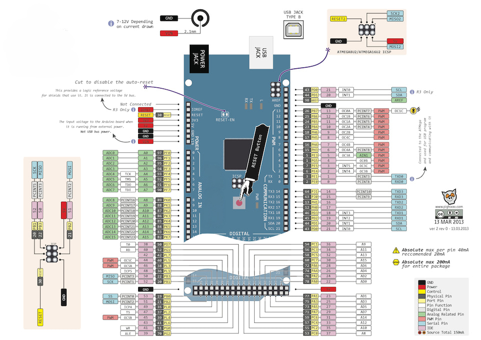
The Mega 2560 R3 has extra SDA and SCL pins. These pins are located next to the AREF pin on the board layout.
Additionally, unlike previous versions, two new pins have been added next to the reset pin on the board: one is the IOREF pin to provide supply/reference from the board to shield modules, and the other is an unconnected pin reserved for future use.
It is compatible with all shields available on the market.
The development board can be powered via the USB connection or an external power supply. The external power supply can be an AC-to-DC adapter or a battery. The adapter can be connected by plugging a 2.1mm center-positive plug into the board's power jack. The battery can be connected using the GND and Vin pin headers on the board.
The USB does not need to be continuously connected for the board to operate. The board can be operated solely with an adapter or battery. In this way, the hardware can be portable and independent from the computer. An external power supply between 6-20V can be used. However, these are limit values. The recommended external supply voltage for the board is between 7-12V. This is because the onboard regulator may not work stably at values below 7V; at values above 12V, it may overheat. The operating voltage of the microcontroller on the board is 5V. The 7-12V voltage supplied via the Vin pin or the power jack is reduced to 5V by the voltage regulator and distributed to the board.
The power pins are as follows:
All 54 digital pins on the board can be used as an input or output. There are also 16 analog input pins. These analog input pins can also be used as digital inputs and outputs in the same way. In other words, there is a total of 70 digital I/O pins on the board. The logic level of all these pins is 5V. Each pin operates with a maximum input/output current of 40 mA. Additionally, some pins have specialized functions. The specialized pins are as follows:
You can review the Pin Mapping Table between the development board and the ATmega2560.
The development board has a number of facilities for communicating with a computer, another microcontroller, or an Arduino® board. The ATmega2560 provides 4 hardware UARTs for TTL (5V) serial communication. The CH340 USB-to-Serial converter on the board establishes a bridge between the ATmega2560 and the computer by creating a virtual COM port. The Arduino® IDE includes a serial monitor that allows simple textual data to be sent to and from the board. The RX and TX LEDs on the board will flash when data is being transmitted. In addition to the 4 hardware serial ports, this number can be increased via software using the SoftwareSerial Library. The ATmega2560 also supports I2C and SPI communication. The Wire Library included with the Arduino® IDE is used to facilitate I2C use, and the SPI Library is used to facilitate SPI communication.
This compatible development board is programmed using the Arduino® IDE. You can start programming by selecting Arduino® Mega or Mega 2560 under the Tools > Board menu in the software. For detailed information, you can review the Arduino® Reference Documents and the Basic Tutorials page. The ATmega2560 chip on the board comes preprogrammed with a special software called a bootloader. Thanks to this, you do not need to use an external hardware programmer when programming the hardware. Communication is established using the original STK500 Protocol. The bootloader software can be bypassed, and code can be uploaded directly via the ICSP header using an External ISP Programmer (External Programmer Guide). Source codes that provide serial communication, like the bootloader software, are also open-source; in the original design, this is called the DFU bootloader and can be reprogrammed with various tools.
If you are unfamiliar with the Arduino® ecosystem, you can check out our Lessons for Arduino® series available on our blog.