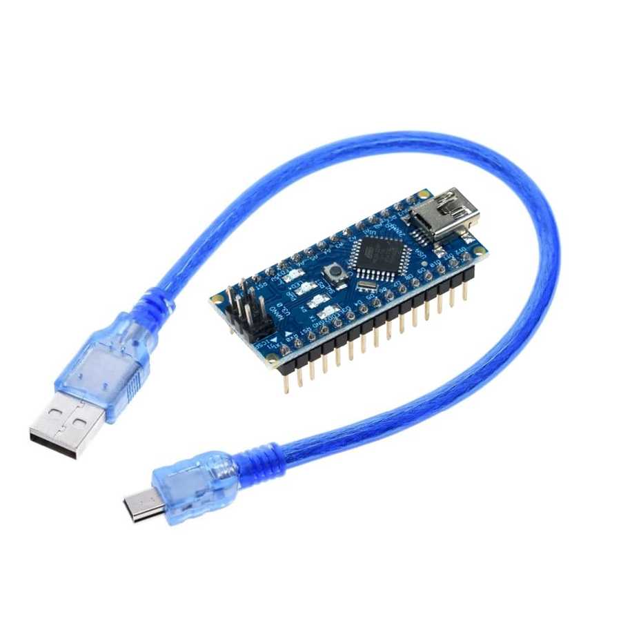
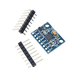
Nano 328 FT232 Development Board Compatible with Arduino (with USB Cable)
For general information about the Arduino® ecosystem and a board selection guide, you can visit the What is Arduino®? page.
Nano 328 FT232 Development Board Compatible with Arduino Package Contents:
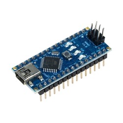
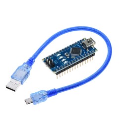
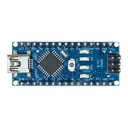
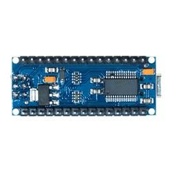
Nano 328 FT232Development Board Compatible with Arduino
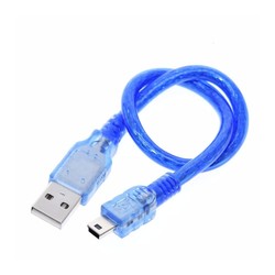
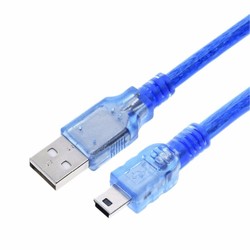
Mini-B USB Cable
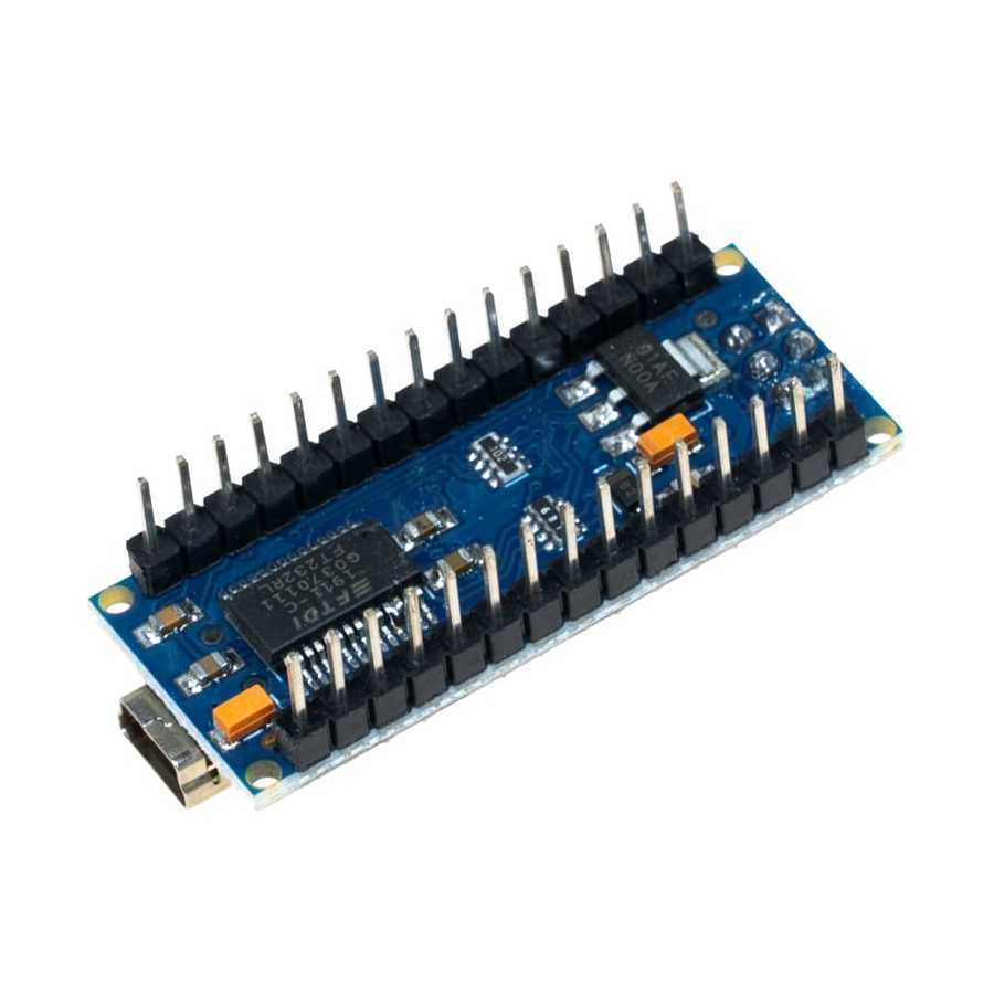
The Nano 328 FT232 development board is an ATmega328 based microcontroller board. It features 14 digital input/output pins (6 of which can be used as PWM outputs), 8 analog inputs, a 16MHz crystal, a USB socket, an ICSP header, and a reset button. The board contains everything needed to support the microcontroller. It can easily be connected to a computer with a USB cable, or powered with an adapter or battery.
The board features an FTDI FT232 USB-to-serial converter for uploading programs and communicating with the computer.
Nano Development Board Compatible with Arduino Technical Specifications:
Microcontroller: ATmega328
Operating Voltage: 5V
Input Voltage (recommended): 7-12V
Input Voltage (limits): 6-20V
Digital I/O Pins: 14 (6 provide PWM output)
Analog Input Pins: 8
DC Current per I/O Pin: 40 mA
DC Current for 3.3V Pin: 50 mA
Flash Memory: 32 KB (ATmega328) of which 2 KB used by bootloader
SRAM: 2 KB (ATmega328)
EEPROM: 1 KB (ATmega328)
Clock Speed: 16 MHz
Length: 45 mm
Width: 18 mm
Weight: 5 g
Power:
The Nano 328 FT232 development board compatible with Arduino can be powered via USB or with an external power supply. The external power supply can be an AC-to-DC adapter or a battery. The adapter and battery can be connected via the GND and Vin pins on the board.
The USB does not have to be constantly connected for the board to operate. The board can be powered only with an adapter or battery. This allows the board to operate independently of the computer.
An external power supply of 6-20V can be used. However, these are limit values. The recommended external power for the board is 7-12V. Because the regulator on the board may not operate stably at values below 7V. It may also overheat at values above 12V.
The operating voltage of the microcontroller on the board is 5V. The 7-12V voltage supplied via the Vin pin or power socket is stepped down to 5V by the voltage regulator on the board and distributed to the board.
The power pins are as follows:
VIN: The input voltage pin for 7-12V when using an external power source.
5V: This pin outputs the 5V from the regulator. If the board is only running over USB (5V), the 5V coming over the USB is directly given as output via this pin. At the same time, a 5V input can be supplied through this pin. If power is supplied to the board via Vin (7-12V), the 5V coming out of the regulator is directly given as output via this pin.
3V3: This is the output pin of the 3.3V regulator located on the board. It can output a max of 50mA.
GND: Ground pins.
Memory:
The ATmega328 has 32 KB of flash memory (of which 2 KB is used by the bootloader). It has 2 KB of SRAM and 1 KB of EEPROM.
Input and Output:
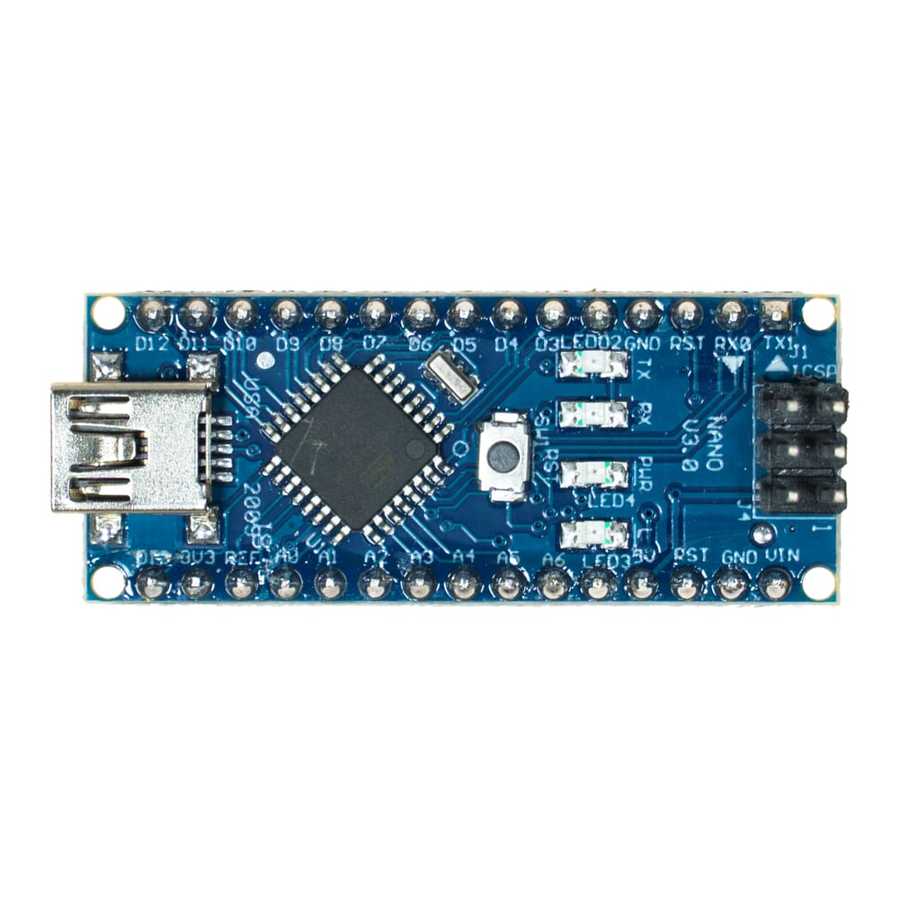
All 14 digital pins on the board can be used as an input or output. There are also 8 analog input pins. These analog input pins can likewise be used as digital inputs and outputs. So there are a total of 20 digital input/output pins on the board. The logic level of all these pins is 5V. Each pin operates with a max input and output current of 40mA. In addition, some pins have different features. The special pins are as indicated below.
Serial Communication, 0 (RX) and 1 (TX): Used to receive (RX) and transmit (TX) TTLserial data. These pins are directly connected to the FT232 USB-to-serial converter on the board. In other words, these pins are also used when uploading code from the computer to the board or when there is mutual communication between the computer and the board. Therefore, to avoid errors when uploading code to the board or communicating, it is beneficial not to use these pins unless necessary.
External Interrupts, 2 (interrupt 0) and 3 (interrupt 1): These pins can be configured to trigger an interrupt on a rising edge, falling edge, or a change in value. For detailed information, you can review theattachInterrupt() function page.
PWM, 3,5,6,9,10 and 11: Can be used as PWM output pins with 8-bit resolution.
SPI, 10 (SS), 11 (MOSI), 12 (MISO), 13 (SCK): These pins are used for SPI communication.
LED, 13: There is a built-in LED connected to digital pin 13 on the board. When the pin is HIGH, the LED turns on; when LOW, it turns off.
Analog, A0-A7: The development board has 8 analog input pins with 10-bit resolution. These pins can also be used for digital input and output. The measurement range of the pins is 0-5V. By using the AREF pin and the analogReference() function, the lower limit can be raised and the upper limit can be lowered.
I2C, pin A4 or SDA and pin A5 or SCL: These pins are used for I2C communication.
AREF: Reference voltage pin for the analog inputs.
Reset: Bring this pin LOW to reset the microcontroller. The reset operation can also be done with the Reset Button on the board.
You can review the pin mapping page between the ATmega328 and the board.
Communication:
The development board has several different options for communicating with a computer, another microcontroller, or an Arduino® board. The ATmega328 provides UART TTL (5V) serial communication over the 0 (RX) and 1 (TX) pins. The FT232 USB-to-serial converter on the board also opens a virtual com port on the computer and establishes a bridge between the ATmega328 and the computer. The Arduino® IDE allows text-based information to be sent and received between the board and the computer with the serial monitor it contains. The RX and TX LEDs on the board will flash when data is being transmitted via the USB between the USB-to-serial converter and the computer.
The board has one hardware serial port. However, this number can be increased via software with the SoftwareSerial library.
The ATmega328 also provides I2C and SPI ports. The Wire library that comes with the Arduino® IDE is used for I2C use, and the SPI library is used to provide SPI communication.
Programming:
The Nano 328 FT232 development board compatible with Arduino is programmed with the Arduino® Software (Arduino® IDE). In the program, you can select Arduino® Nano under the Tools > Board tab and start programming. For detailed information, you can review the reference and basic functions tutorials page. The ATmega328 on the board comes preburned with a special software called a bootloader. This way, you don't need to use an extra programmer when programming the board. Communication is provided by the original STK500 protocol.
If you are unfamiliar with the Arduino® ecosystem, you can check out our Lessons for Arduino® series on our blog.
Note: You can review the Nano Compatible Proto Shield product, which allows for easier connection of sensors and various input/output components to the development board.