Brand
:
Robotistan
Product Code
:
17883


Out Of Stock
Notify me when its in stock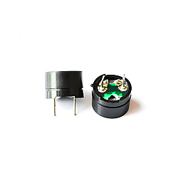

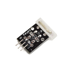
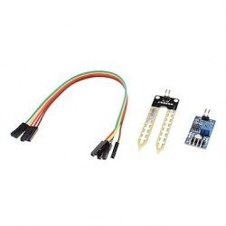

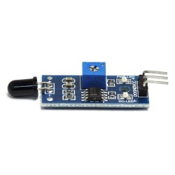
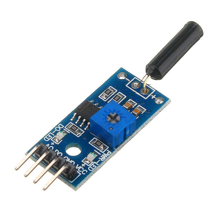
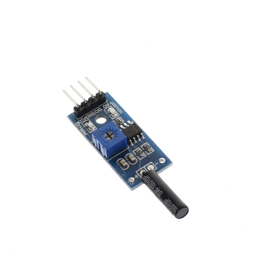
Tilt Sensor Module
The tilt sensor module is equipped with a tilt sensor and a potentiometer. You can attach it to any object, and it detects whether the object is tilted or not. It is simple to use because it returns a digital output. It uses the SW-460D or SW-520D tilt sensor. This tilt sensor is NOT a mercury type; it is a ball rolling type.
It comes with an M3 mounting hole to make it easy to attach to any object. A power LED and a status LED are included on the module for visual indication.
This module will output logic LOW when the sensor is tilted below the threshold angle, and HIGH when it is tilted above the threshold angle. The threshold angle varies from 45 degrees to 130 degrees. In addition to the threshold angle, angular velocity also affects the tilt module. It can also be used as a vibration sensor!
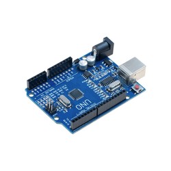
This module can be interfaced with any microcontroller that has a digital input, such as PIC, SK40C, SK28A, SKds40A, and Arduino® boards, for tilt detection. In addition, interfacing the module with a relay module creates a tilt switch.
Product Features:
* If DO does not work, you may need to adjust the onboard potentiometer to the center position.
Application:
Attending lectures as a student is not very fun. In fact, there are only 2 situations where lectures can be interesting: either the lecturer is very nice, or you have a deep interest in the subject. Unfortunately, most university students stay up late at night either to finish their assignments and projects, play games, or hang out, and then suffer from lack of sleep. Even worse, they may have to attend an 8:00 AM lecture the next day...
You slowly drift off into your imagination and fall asleep during the lecture. Everything is comfortable and nice until your lecturer throws you out. That would be embarrassing, wouldn't it?
Here is the Lecture Alarm! An alarm that automatically turns on when your head gets heavy and starts to tilt. Falling asleep in class and getting kicked out by your lecturer is now just a thing of imagination!

Setup:
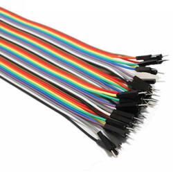
Materials:

Building the Circuit:
The diagram above shows the connection of the CT-UNO, tilt sensor module, and buzzer.
Pin Connection of the Tilt Sensor Module:

Pin Connection of the NPN Transistor N2222:
The diagram above shows the pins of the NPN transistor. Why do I use a transistor? To prevent a high current drop. When working with a buzzer, it is recommended not to connect it directly to your UNO or any microcontroller.
CT-UNO uses the ATmega328p. The maximum current per I/O pin is 40mA. Please also note: the maximum total supply current is 200mA.
If you do not know the specifications of the buzzer, you can measure them manually.
Step 1: Your buzzer should have a "+" terminal and a "-" terminal marked. Connect the "+" terminal of the buzzer to the positive terminal of the 5V power supply.
Step 2: Use a digital multimeter (DMM) to connect the "-" terminal of the buzzer.
Step 3: The negative terminal of the DMM is connected to the negative terminal of the 5V power supply.

Measuring the current passing through the buzzer with a 5V power supply (I = 2.93mA)
We can see that the current drawn by the buzzer is 2.93mA. Although this does not exceed the current limit that an I/O pin of an Arduino® board can provide, adding a transistor is still safer.
If the buzzer draws more current than the uC I/O can provide, you can try adding a resistor according to the current, but it probably will not work or will operate outside the specifications. An NPN transistor will help you.
Program
[code lang=”c” highlight=””]
#define Tilt 2 //Digital output from tilt sensor module is connected to D2
#define BUZZER 3 //LED at D3 pin
void setup() {
//setup the input or output pin
pinMode(BUZZER, OUTPUT);
pinMode(Tilt, INPUT);
digitalWrite(BUZZER, LOW); //off LED
}
void loop() {
if(digitalRead(Tilt)) //if the DO from Tilt sensor is low, no tilt detected.
//You might need to adjust the potentiometer to get reading
digitalWrite(BUZZER,HIGH);
else
digitalWrite(BUZZER,LOW);
}[/code]
LCD Keypad Shield:
You can also use an LCD to display some messages. I am using an LCD Keypad Shield.

Setup:
Build the circuit with the LCD Keypad Shield!
NOTE: The LCD Keypad Shield uses pins 4 to 9. Do not use these pins for other purposes.
Program
[code lang=”c” highlight=””]
/*
The circuit:
* 16×2 character LCD to Arduino® UNO
* LCD RS pin to digital pin 8
* LCD Enable pin to digital pin 9
* LCD D4 pin to digital pin 4
* LCD D5 pin to digital pin 5
* LCD D6 pin to digital pin 6
* LCD D7 pin to digital pin 7
* LCD R/W pin to ground
Tilt Sensor module to Arduino® UNO
*VCC to 5V
*GND to GND
*Do to D2
*AO of tilt sensor is not used
*/
// include the library code:
#include
#include
#define Tilt 2 //Digital output from tilt sensor module is connected to D2
#define BUZZER 3 //LED at D3 pin
// initialize the library with the numbers of the interface pins
LiquidCrystal lcd(8, 9, 4, 5, 6, 7);
void setup() {
//setup the input or output pin
pinMode(BUZZER, OUTPUT);
pinMode(Tilt, INPUT);
digitalWrite(BUZZER, LOW); //off LED
// set up the LCD’s number of columns and rows:
lcd.begin(16, 2);
// Print a message to the LCD.
lcd.print(” Lecture”);
lcd.setCursor(0,1);
lcd.print(” Alarm”);
delay(1000); //delay for 1 second
lcd.clear();
}
void loop() {
if(digitalRead(Tilt)) //if the DO from Tilt sensor is low, no tilt detected. You might need to adjust the potentiometer to get reading
{
digitalWrite(BUZZER,HIGH);
lcd.setCursor(0, 0); //move LCD cursor
lcd.print(“SLEEPING”); //Display message
}
else
{
digitalWrite(BUZZER,LOW);
lcd.setCursor(0, 0); //move LCD cursor
lcd.print(“AWAKE “); //Display message
}
}[/code]