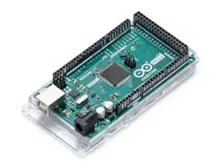
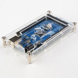
Original Arduino® Mega 2560 R3
Product Contents:
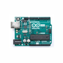
Mega 2560 R3 Development Board Compatible with Arduino (CH340) model, you can check out the related product page.
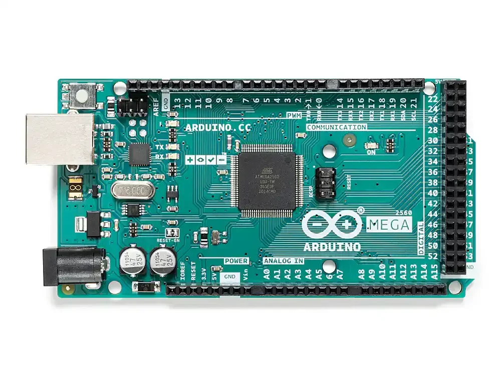
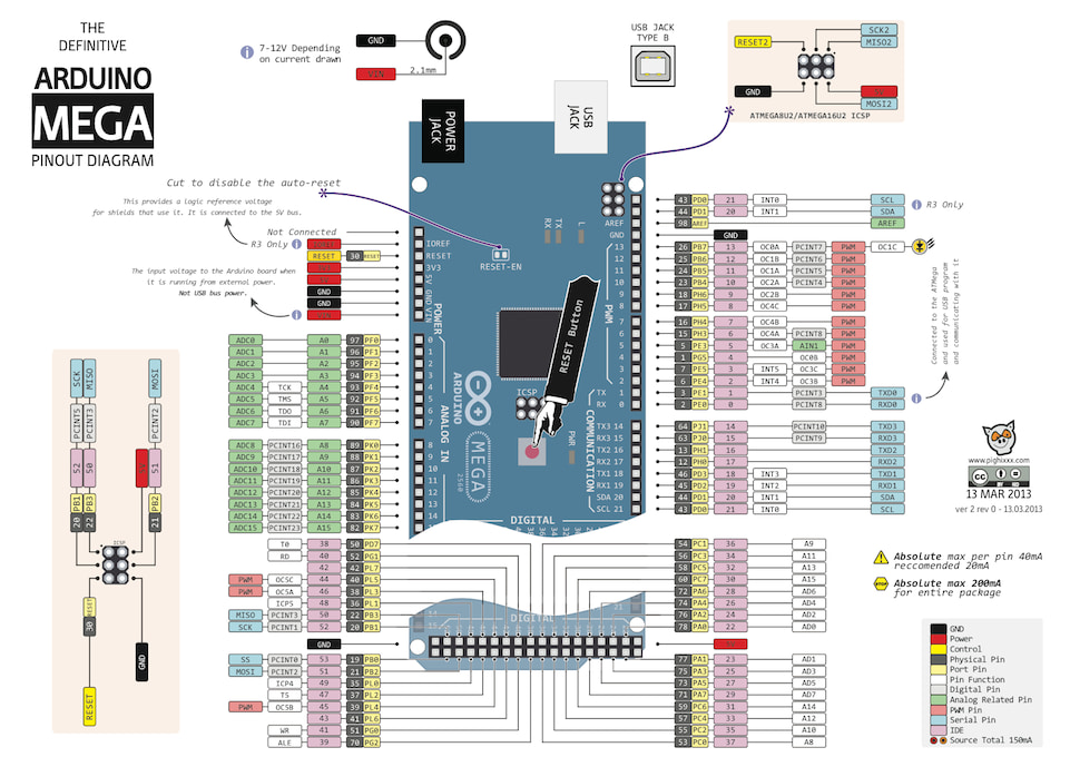
Arduino® Mega 2560 is a microcontroller board based on the ATmega2560. It has 54 digital input/output pins (15 of which can be used as PWM outputs), 16 analog inputs, 4 UARTs (hardware serial ports), a 16 MHz crystal, USB socket, power jack, ICSP connector, and reset button. The board includes everything required for the microcontroller to operate. It can be easily connected to a computer via a USB cable or powered with an adapter or battery.
If you are new to Arduino®, you can check out our Lessons for Arduino® series on our blog site.
Mega has an ATmega16u2 USB-to-serial converter on the board for uploading programs and communicating with the computer. The Rev 2 version had an ATmega8u2.
Many improvements have been made on the Mega Rev 3 version compared to the Rev 2 version to provide ease of use and more stable operation. You can review the historical development of Arduino® boards through the hardware index.
Original Arduino® Mega 2560 R3 Technical Specifications:
- Microcontroller: ATmega2560
- Operating Voltage: 5V
- Input Voltage (recommended): 7-12V
- Input Voltage (limit): 6-20V
- Digital I/O Pins: 54 (15 PWM outputs)
- Analog Input Pins: 16
- Current per I/O Pin: 40 mA
- Current for 3.3V Output: 50 mA
- Flash Memory: 256 KB (ATmega2560), 8 KB of which is used by the bootloader
- SRAM: 8 KB (ATmega2560)
- EEPROM: 4 KB (ATmega2560)
- Clock Speed: 16 MHz
- Length: 101.6 mm
- Width: 53.4 mm
- Weight: 36 g
Original Arduino® Mega 2560 R3 Power:
Arduino® Mega can be powered via USB or an external power supply. The external power supply can be an AC-DC adapter or a battery. The adapter can be connected through the 2.1 mm center-positive power jack on the board. The battery can be connected through the GND and Vin pins on the board.
USB does not have to be connected continuously for the board to operate. The board can be operated only with an adapter or battery. In this way, the board can work independently from the computer.
An external power supply between 6-20V can be used. However, these values are limit values. The recommended external supply for the board is between 7-12V. This is because the regulator on the board may not operate stably at values below 7V and may overheat at values above 12V.
The operating voltage of the microcontroller on the Mega board is 5V. The 7-12V voltage supplied through the Vin pin or power jack is reduced to 5V by the voltage regulator on the board and distributed to the board.
The power pins are as follows:
- VIN: Voltage input pin between 7-12V when using an external power supply.
- 5V: This pin provides the 5V output from the regulator. If the board is powered only via USB (5V), the 5V coming from USB is directly provided as output through this pin. If the board is powered through Vin (7-12V) or the power jack (7-12V), the 5V from the regulator is directly provided as output through this pin.
- 3V3: This is the output pin of the 3.3V regulator on the board. It can provide a maximum output of 50mA.
- GND: These are the ground pins.
Original Arduino® Mega 2560 R3 Memory:
The ATmega2560 has 256 KB of flash memory (8 KB of which is used by the bootloader). It has 8 KB SRAM and 4 KB EEPROM.
Original Arduino® Mega 2560 R3 Input and Output:
All 54 digital pins on the Mega can be used as input or output. There are also 16 analog input pins. These analog input pins can also be used as digital inputs and outputs. In other words, there are a total of 70 digital input/output pins on the board. The logic level of all these pins is 5V. Each pin operates with a maximum input and output current of 40mA. In addition, some pins have different features. The special pins are listed below.
- Serial Communication, Serial: 0 (RX) and 1 (TX), Serial1: 19 (RX) and 18 (TX), Serial2: 17 (RX) and 16 (TX), Serial3: 15 (RX) and 14 (TX): Used to receive (RX) and transmit (TX) TTL serial data. Pins 0 and 1 are directly connected to the ATmega16u2 USB-to-serial converter on the board. In other words, these pins are also used when uploading code from the computer to the board or when two-way communication is performed between the computer and Mega. Therefore, to avoid errors while uploading code or communicating, it is useful not to use these pins unless necessary.
- External Interrupts, 2 (interrupt 0), 3 (interrupt 1), 18 (interrupt 5), 19 (interrupt 4), 20 (interrupt 3), 21 (interrupt 2): These pins can be used as rising edge, falling edge, or change interrupt pins. For detailed information, you can review the attachInterrupt() function page.
- PWM, 2-13 and 44-46: Can be used as PWM output pins with 8-bit resolution.
- SPI, 53 (SS), 51 (MOSI), 50 (MISO), 52 (SCK): These pins are used for SPI communication.
- LED, 13: There is a built-in LED connected to pin 13 on the Mega. When the pin is set HIGH, the LED will turn on; when set LOW, the LED will turn off.
- Analog, A0-A15: Mega has 16 analog input pins with 10-bit resolution. These pins can also be used as digital inputs and outputs. The measurement range of the pins is 0-5V. By using the AREF pin and the analogReference() function, the lower limit can be raised and the upper limit can be lowered.
- I2C, pin 20 or SDA pin and pin 21 or SCL pin: These pins are used for I2C communication.
- AREF: Reference pin for analog input.
- Reset: When the microcontroller needs to be reset, this pin is set LOW. Resetting can also be performed using the Reset Button on the board.
You can review the pin mapping page between Arduino® Mega and ATmega2560.
Original Arduino® Mega 2560 R3 Communication:
Arduino® Mega has several different options for communicating with a computer, another Arduino® board, or a microcontroller. The ATmega2560 offers 4 hardware UART TTL (5V) serial communication ports. The ATmega16u2 USB-to-serial converter on the board also opens a virtual COM port on the computer and creates a bridge between the ATmega2560 and the computer. The serial monitor included in the Arduino® computer program allows text-based information to be sent and received between Arduino® and the computer. When USB communication occurs between the USB-to-serial converter and the computer, the RX and TX LEDs on the board will light up.
Mega has 4 hardware serial ports. However, this number can be increased through software with the SoftwareSerial library.
The ATmega2560 also provides I2C and SPI ports. The Wire library included with the Arduino® computer program is used for I2C, and the SPI library is used to enable SPI communication.
Original Arduino® Mega 2560 R3 Programming:
The Arduino® Mega board is programmed with the Arduino® computer program (Arduino® IDE). In the program, you can select Arduino Mega under the Tools > Board tab and start programming. For detailed information, you can review the reference and basic functions pages. The ATmega2560 on the Arduino® Mega comes with special software called a bootloader installed. Thanks to this, you do not need to use an extra programmer while programming the board. Communication is provided with the original STK500 protocol.
Bypassing the bootloader software, the board can be programmed directly through the microcontroller’s ICSP header with an ISP programmer (Reference).
Like the bootloader software, the source firmware inside the ATmega16u2 is also open source. This software is called the DFU bootloader. It can be reloaded using Atmel's FLIP software (Windows) or DFU programmer (Mac OS X and Linux). Or, as with the ATmega2560, the 16u2 can be programmed with an ISP programmer. The software inside both the ATmega2560 and the 16u2 is always shipped in its most up-to-date version. Therefore, you do not need to change this software unless necessary.
Original Arduino® Mega 2560 R3 USB Overcurrent Protection:
The resettable fuse on the Arduino® Mega protects the computer’s USB port from short circuits or overcurrent consumption. When the board draws more than 500mA from the computer’s USB port, it automatically cuts off the power it receives from USB for protection. When the overcurrent condition or short circuit is removed, the fuse returns to normal and the connection is re-established.
Note: The product content includes only Arduino® Mega R3; USB cable and adapter are not included. For USB cable, adapter, and quick start book, you can review the promotional Combo Kit product.
Documents: