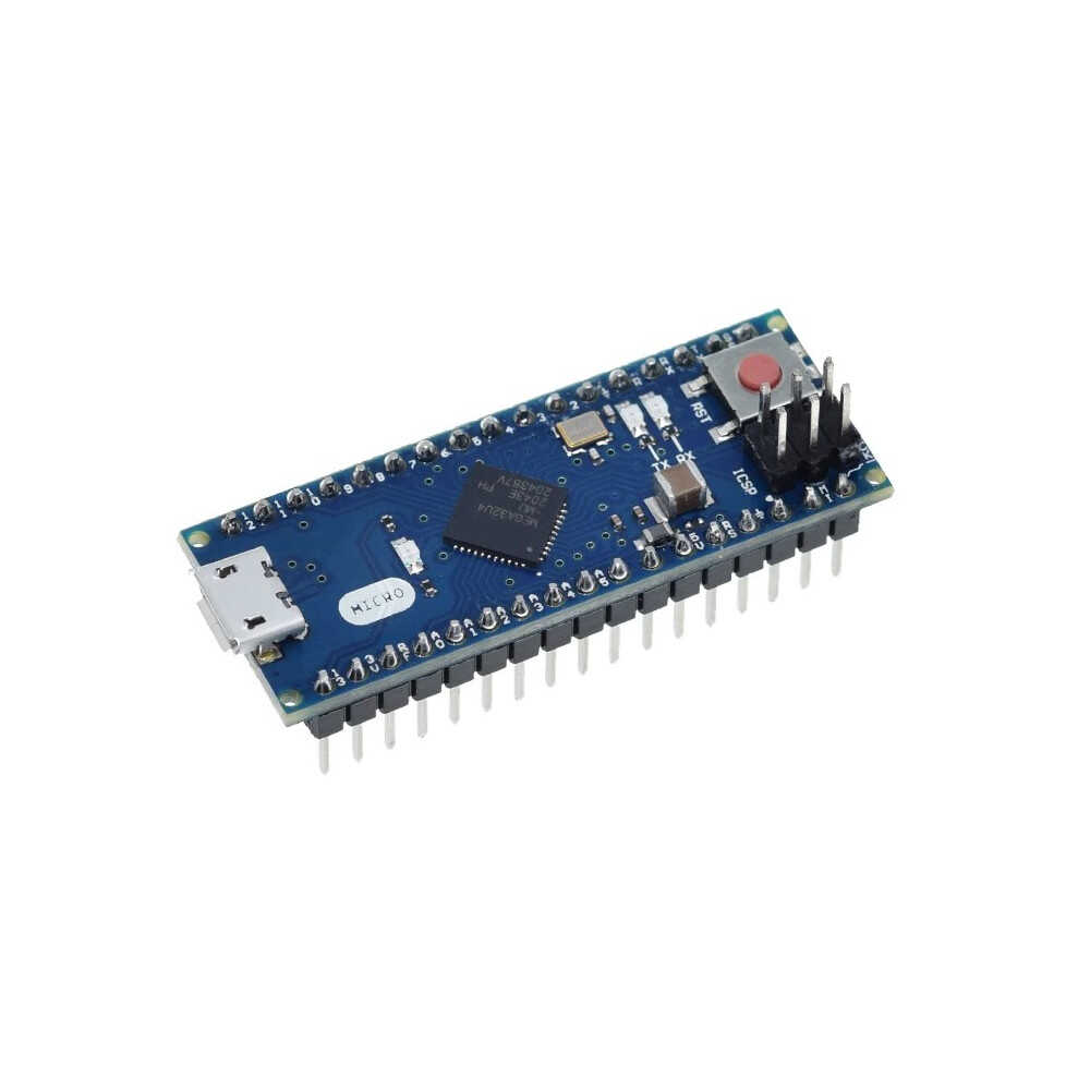
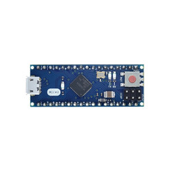
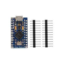
The Micro Development board compatible with Arduino, based on the Arduino® Micro design, is an ATmega32u4 based microcontroller board. The product also includes a USB cable for computer connection.
It features 20 digital input/output pins (7 of which can be used as PWM outputs, 12 as analog inputs), a 16MHz crystal, a micro USB socket, an ICSP header, and a reset button. The board contains everything needed to support the microcontroller. It can easily be connected to a computer with a USB cable, or powered with an adapter or battery.
The biggest feature that distinguishes the Micro development board compatible with Arduino from many other development boards is that the ATmega32u4 has built-in USB communication. There is no need for a secondary USB-to-serial converter processor like the 16u2. This allows the Micro to be used by connecting it to a computer as a mouse, keyboard, etc., in addition to a virtual com port (CDC).
Micro Development Board Compatible with Arduino Technical Specifications:
Microcontroller ATmega32u4
Operating Voltage 5V
Input Voltage (recommended) 7-12V
Input Voltage (limits) 6-20V
Digital I/O Pins 20 (7 provide PWM output, 12 analog inputs)
Analog Input Pins 12
DC Current per I/O Pin 40 mA
DC Current for 3.3V Pin 50 mA
Flash Memory 32 KB (ATmega32u4) of which 4 KB used by bootloader
SRAM 2.5 KB (ATmega32u4)
EEPROM 1 KB (ATmega32u4)
Clock Speed 16 MHz
Length 48 mm
Width 18 mm
Weight 13 g
Power:
The Micro development board compatible with Arduino can be powered via the USB connection or with an external power supply. The external power supply can be an AC-to-DC adapter or a battery. The adapter and battery can be connected via the GND and Vin pins on the board.
The USB does not have to be constantly connected for the board to operate. It can be powered only with an adapter or battery. This allows the board to operate independently of the computer.
An external power supply of 6-20V can be used. However, these are limit values. The recommended external power for the board is 7-12V. Because the regulator on the board may not operate stably at values below 7V. It may also overheat at values above 12V.
The operating voltage of the microcontroller on the Micro development board is 5V. The 7-12V voltage supplied via the Vin pin or power socket is stepped down to 5V by the voltage regulator on the board and distributed to the board.
The power pins are as follows:
VI: The input voltage pin for 7-12V when using an external power source.
5V: This pin outputs the 5V from the regulator. If the board is only running over USB (5V), the 5V coming over the USB is directly given as output via this pin. If power is supplied to the board via Vin (7-12V) or the power socket (7-12V), the 5V coming out of the regulator is directly given as output via this pin.
3V3: This is the output pin of the 3.3V regulator located on the board. It can output a max of 50mA.
GND: Ground pins.
Memory:
The ATmega32u4 has 32 KB of flash memory (of which 4 KB is used by the bootloader). It has 2.5 KB of SRAM and 1 KB of EEPROM.
Input and Output:
All 20 digital pins on the Micro can be used as an input or output. The logic level of all pins is 5V. Each pin operates with a max input and output current of 40mA. In addition, some pins have different features. The special pins are as indicated below.
Serial Communication, 0 (RX) and 1 (TX): Used to receive (RX) and transmit (TX) TTLserial data. Note that the Serial class is used for USB (CDC) communication on the Micro. The Serial1 class must be used for serial communication on pins 0 and 1.
External Interrupts, 3 (interrupt 0), 2 (interrupt 1), 0 (interrupt 2), 1 (interrupt 3), 7 (interrupt 4): These pins can be configured to trigger an interrupt on a rising edge, falling edge, or a change in value. For detailed information, you can review theattachInterrupt() function page.
PWM, 3,5,6,9,10,11 and 13: Can be used as PWM output pins with 8-bit resolution.
SPI, on the ICSP Header: These pins are used for SPI communication. Note that the SPI pins on the ICSP header are not connected to any other pins on the board. So unlike the Uno development board, these pins are not connected to pins 10, 11, 12 and 13. If you are going to use a shield that does SPI communication, the shield must have a 3x2 pin ICSP header. Otherwise, the shield cannot be used with the Micro.
LED, 13: There is a built-in LED connected to the 13th pin on the Micro. When the pin is made HIGH the LED will turn on, when it is made LOW the LED will turn off.
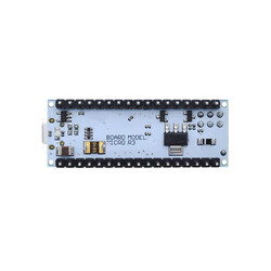
Analog, A0-A5 and A6-A11 (also digital pins 4,6,8,9,10 and 12): The Micro development board has 12 analog input pins with 10-bit resolution. The pins from A0-A5 are in the analog pin section just like on the Uno development board. Those between A6-A11 are in the digital pin section and are connected to digital pins 4, 6, 8, 9, 10, and 12 respectively. The pins are indicated on the bottom of the board. All analog pins can also be used for digital input and output. The measurement range of the pins is 0-5V. By using the AREF pin and the analogReference() function, the lower limit can be raised and the upper limit can be lowered.
I2C, pin 2 or SDA and pin 3 or SCL: These pins are used for I2C communication. While the pins are connected to A4 and A5 on the Uno development board; they are connected to pins 2 and 3 on the Micro development board.
AREF: Reference voltage pin for the analog inputs.
Reset: Bring this pin LOW to reset the microcontroller. The reset operation can also be done with the Reset Button on the board.
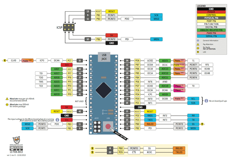
You can review the pin mapping page between the Micro development board compatible with Arduino and the ATmega32u4.
Communication:
The Micro development board compatible with Arduino has several different options for communicating with a computer, another microcontroller board, or an Arduino® board. The ATmega32u4 provides UART TTL (5V) serial communication over the 0 (RX) and 1 (TX) pins. The 32u4 connects to a computer via USB, opening a virtual com port and allowing serial (CDC) communication. The Micro development board allows text-based information to be sent and received between the Micro board and the computer thanks to the serial monitor included in the computer program. The RX and TX LEDs on the board will flash when data is being transmitted via the USB connection to the computer.
The Micro development board has one hardware serial port. However, this number can be increased via software with the SoftwareSerial library.
The ATmega32u4 also provides I2C and SPI ports in the same way. The Wire library that comes with the Arduino® IDE is used for I2C use, and the SPI library is used to provide SPI communication.
The Micro development board can be introduced to the computer as a mouse, keyboard, etc. and can be used with the Keyboard and Mouse classes.
Programming:
The Micro development board compatible with Arduino can be programmed with the Arduino® computer software (Arduino® IDE). In the program, you can select Arduino® Micro under the Tools > Board tab and start programming. For detailed information, you can review the reference and basic functions tutorials page. The ATmega32u4 on the Micro development board compatible with Arduino comes preburned with a special software called a bootloader. This way, you don't need to use an extra programmer when programming the board. Communication is provided by the original AVR109 protocol.
The resettable polyfuse on the Micro development board compatible with Arduino protects the computer's USB port from short circuits or overcurrent consumption situations. When the board draws more than 500mA from the computer USB port, the board automatically cuts the power it receives from the USB for protection. When the overcurrent situation or short circuit is removed, the fuse returns to normal and the connection is re-established.
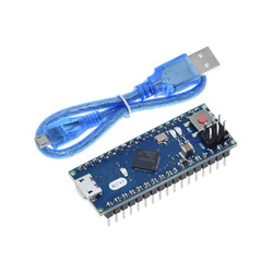
Micro Development Board Compatible with Arduino Package Contents:
Micro Development Board
Micro USB Cable
If you are unfamiliar with Arduino® boards, you can check out our Lessons for Arduino® series on our blog.
Micro Development Board Compatible with Arduino Documents: