Brand
:
Robotistan
Product Code
:
11624
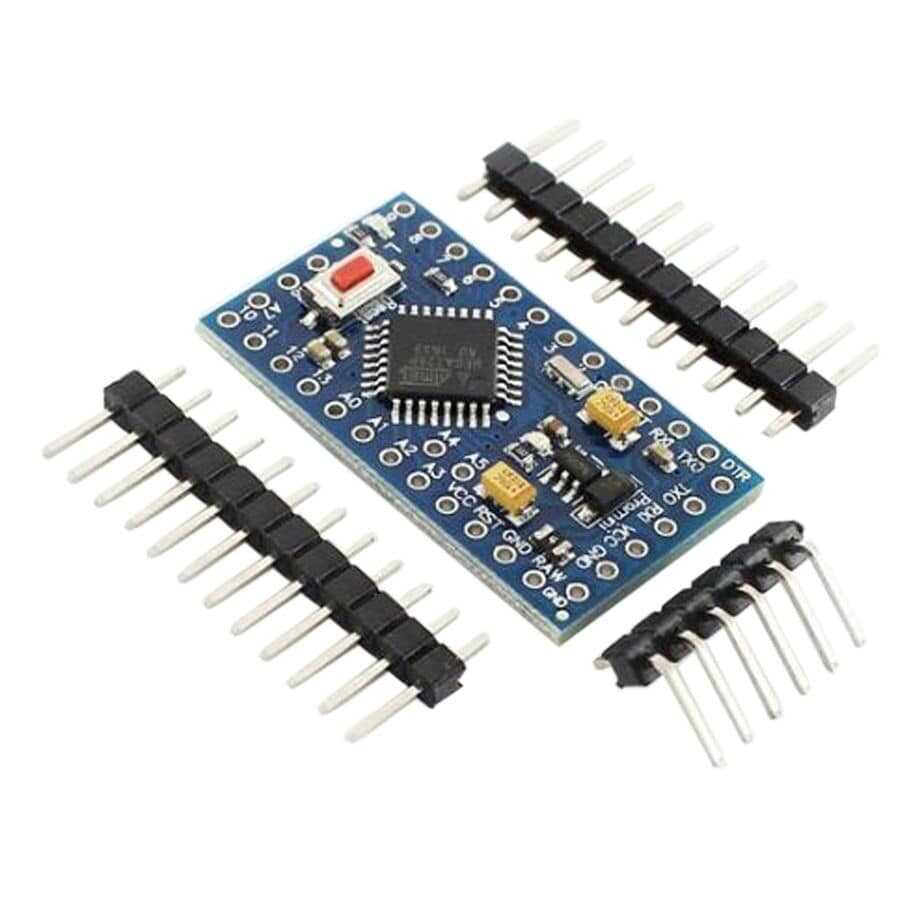

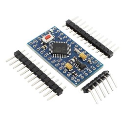
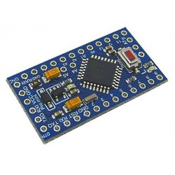
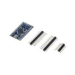
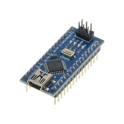
The Pro Mini 328 3.3V / 8 MHz development board compatible with Arduino is shipped unsoldered along with male headers. Manufactured based on the original Arduino® Pro Mini design, the Pro Mini 328 3.3V / 8 MHz development board is very similar to the Mini model in features, but they cannot be used interchangeably because their pinout is different.
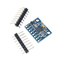
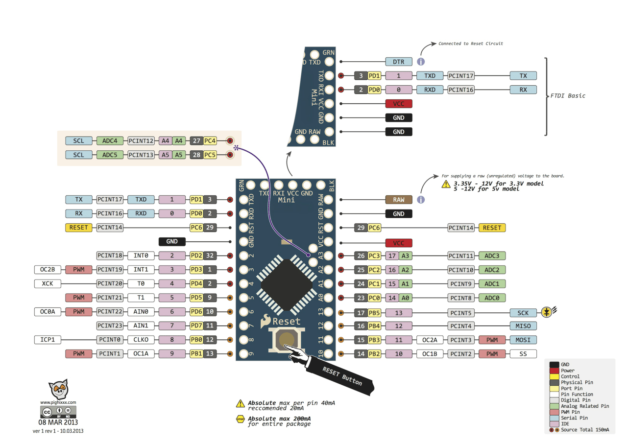
The Pro Mini 328 3.3V / 8 MHz development board is an ATmega328 based microcontroller board. It features 14 digital input/output pins (6 of which can be used as PWM outputs), 8 analog inputs, an 8 MHz crystal, and a reset button. It is specifically designed to be used on a breadboard and in tight spaces where size is important. The board does not have a built-in USB socket and programmer. To upload code to the board, a USB-Serial Converter or a similar external USB-to-serial converter module must be used.
There is another version of the Pro Mini 328 3.3V/8 MHz development board which is 5V/16 MHz.
The Pro Mini 328 3.3V / 8 MHz development board can be powered via the 5V pin or with an external power supply. The external power supply can be an AC-to-DC adapter or a battery. The adapter or battery can be connected via the GND and RAW pins on the board.
An external power supply of 7-12V can be used. Applying a voltage above 12V may damage the board.
The operating voltage of the microcontroller on the board is 5V. The 7-12V voltage supplied via the RAW pin is stepped down to 5V by the voltage regulator on the board and distributed to the board.
The power pins are as follows:
Note: In this 3.3V model you are reviewing, the board regulator is adjusted accordingly, please pay attention to the power connections.
The ATmega328 has 32 KB of flash memory (of which 0.5 KB is used by the bootloader). It has 2 KB of SRAM and 1 KB of EEPROM.
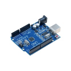
All 14 digital pins on the Pro Mini 328 3.3V / 8 MHz development board can be used as an input or output. There are also 8 analog input pins. Although ATmega328 is used, while there are 6 analog input pins on the UNO, thanks to the package of the ATmega328 microcontroller used on the Pro Mini 328 3.3V / 8 MHz development board, it has 8 analog input pins. These analog input pins can likewise be used as digital inputs and outputs. So there are a total of 22 digital input/output pins on the board. The logic level of all these pins is 5V. Each pin operates with a max input and output current of 40mA. In addition, some pins have different features. The special pins are as indicated below:
You can review the pin mapping page between the ATmega328 and the board.
The Pro Mini 328 3.3V / 8 MHz development board has several different options for communicating with a computer, another microcontroller, or an Arduino® board. The ATmega328 provides UART TTL (5V) serial communication over the 0 (RX) and 1 (TX) pins.
The board has one hardware serial port. However, this number can be increased via software with the SoftwareSerial library.
The ATmega328 also provides I2C and SPI ports. The Wire library that comes with the Arduino® IDE is used for I2C use, and the SPI library is used to provide SPI communication.
The Pro Mini 328 3.3V / 8 MHz development board compatible with Arduino is programmed with the Arduino® IDE. A USB-Serial Converter or other USB-to-serial converter modules can be used to program the board. For detailed installation, you can review the Arduino® Pro Mini Usage Guide page.
After making the programmer connections, you can select Arduino® Pro or Pro Mini under the Tools > Board tab on the Arduino® software and start programming. For detailed information, you can review the reference and basic functions tutorials page. The ATmega328 on the board comes preburned with a special software called a bootloader. This way, you don't need to use an extra programmer when programming the board. Communication is provided by the original STK500 protocol.
By bypassing the bootloader software, the board can be programmed directly via the microcontroller's ICSP pins with an ISP programmer. For detailed information about ICSP pin connections, you can review the Pro Mini Bootloader Installation Guide page.
If you are unfamiliar with the Arduino® ecosystem, you can check out our Lessons for Arduino® series on our blog.
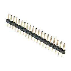
Note: The product you are reviewing is shipped unsoldered along with male headers, you can do the soldering process suitable for your project.