Brand
:
SeeedStudio
Product Code
:
17414


Out Of Stock
Notify me when its in stock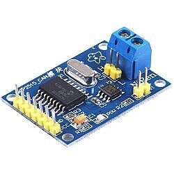
The CAN-BUS communication protocol is widely used in the automotive sector, providing communication between all electronic components inside the car such as sensors, screens, etc. You can access detailed information about CAN-BUS from this link.
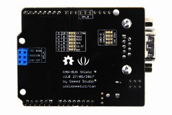
The CAN-BUS Shield V2 allows your development board to communicate with your vehicle's ECU. In this way, by using your Arduino® boards, you can instantly access a lot of information about your vehicle such as engine speed, coolant temperature, gas pedal position, etc.
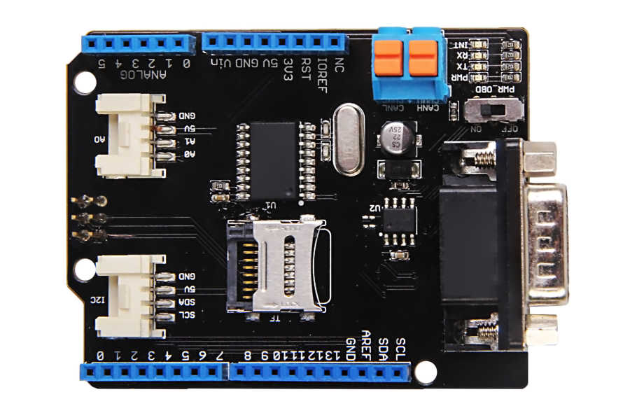
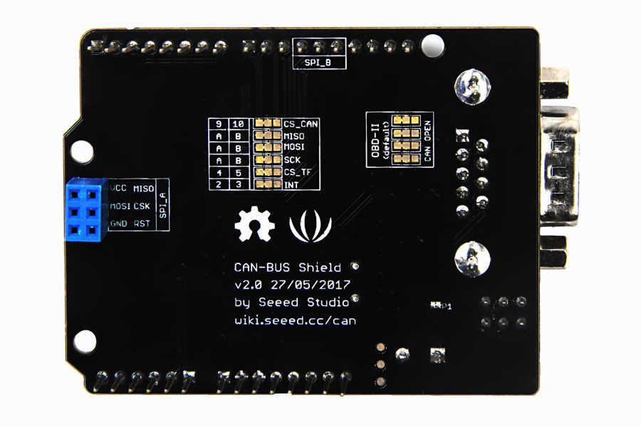
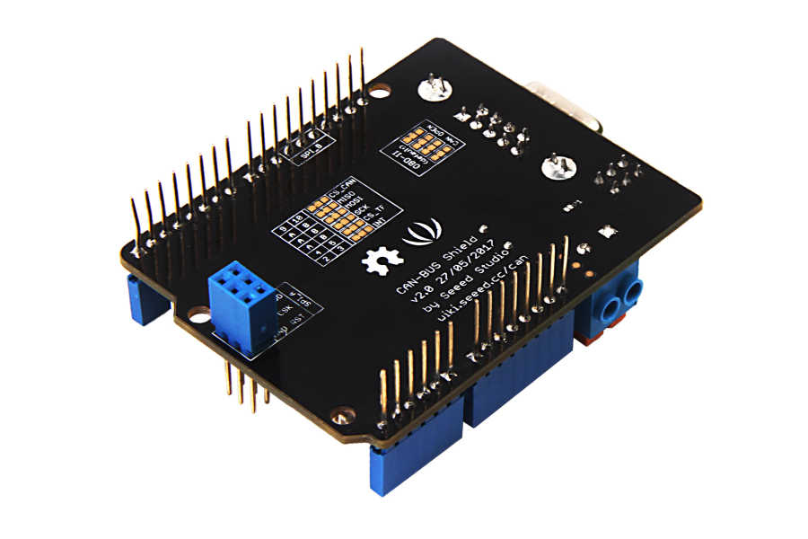
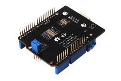
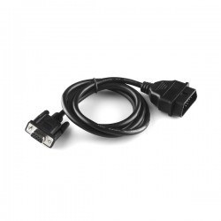
In the CAN-BUS Shield V2 version, the MCP2515 CAN-BUS controller IC and the MCP2551 CAN transceiver IC are included, just like in the V1.2 version. The biggest improvement of the V2 version is that it allows the pin layout of the DB9 connector to be changed to be compatible with the OBD-II or standard CAN interface (it comes with the OBD-II pin layout by default). Additionally, the TF (micro SD) card slot on the board is highly useful for data logging. The CS pin of the SD card can be set to either D4 or D5. Similarly, the INT pin can be changed to either D2 or D3 via the jumpers located on the back of the board. If you want to use more than 2 CAN-BUS Shields, you need to cut the P1 jumper on the back of the board.
Since the D0/D1 pins are generally used when connecting the Arduino® to a computer, the Grove connector for serial communication is positioned to use the A0/A1 pins. Likewise, the Grove connector for I2C communication is connected to use the SDA/SCL pins instead of the A4/A5 pins. Since both Grove connectors are positioned horizontally, they offer convenience when you want to connect different modules.
It is compatible with the Arduino® UNO R3, Arduino® Mega 2560 R3, and Arduino® Leonardo boards.