 EN
EN


Brand
:
Robotistan
Product Code
:
15232
Out Of Stock
Notify me when its in stock
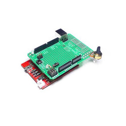
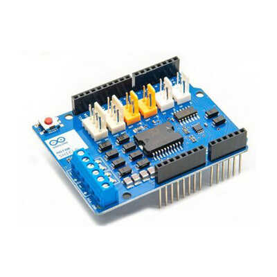
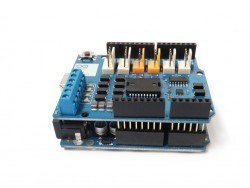
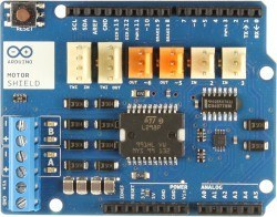
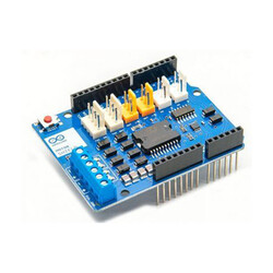
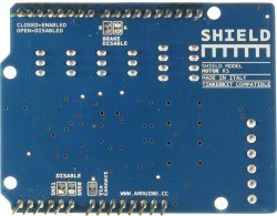
It is a budget-friendly and highly compatible development board based on the original Arduino® Motor Shield design. It is 100% compatible with all libraries and sample codes used with the original shield. As Robotistan, we also recommend that you always use original products for the highest stability in your projects.
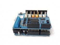
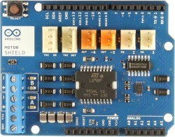
The Motor Shield Compatible with Arduino is a full-bridge motor driver board based on the L298 motor driver IC.
It works fully compatible with the original libraries and sample codes. It can drive two separate 2A DC motors or one 2A stepper motor.
You can control the speed and direction of the motors independently of each other. At the same time, thanks to the Current Sense feature, you can detect the current drawn by each motor separately. There are 6 extra connectors on the board for rapid prototyping.
The Motor Shield Compatible with Arduino should only be powered via an external source for ideal performance.
The L298 IC has 2 separate power connections; one for logic, the other for motor supply. Since the required motor current will mostly exceed the maximum current the USB can provide, it is recommended to use an external adapter or battery.
The external supply should be connected from the `Vin` and `GND` terminals on the driver (paying attention to the poles). It is always recommended that power be supplied from the terminal on the driver.
If power is supplied directly from the development board, the current drawn by the motors will pass through the board and reach the driver. Since the `Vin` line of development boards is usually designed to carry a maximum of 1A current, your board may be damaged when this value is exceeded.
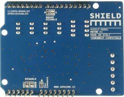
There is a solder jumper (short circuit path) named "Vin Connect" under the driver board. This jumper connects the `Vin` terminal on the driver with the `Vin` pin of the development board.
If a voltage between 5V - 7V is to be supplied to the driver, the system may not work stably as this range will be low for the regulator of the development board. To prevent this situation, the thin path in the middle of the "Vin Connect" jumper is carefully scraped and cut with the help of a utility knife. In this way, the power line of the driver and the power line of the control board are separated from each other, and an external 5V must be supplied to your development board.
The motor shield has two independent channels named A and B. The control of each of these channels is provided by 4 pins, and a total of 8 digital/analog pins are used.
The channels can be used separately to drive 2 independent DC motors, or used together to control 1 unipolar or bipolar stepper motor.
Shield Pin Usage Table:
| Function | Channel A Pin | Channel B Pin |
| Direction | D12 | D13 |
| PWM (Speed Control) | D3 | D11 |
| Brake | D9 | D8 |
| Current Sensing | A0 | A1 |
If you do not need the "Brake" and "Current Sensing" features, you can cancel these features by cutting the corresponding solder jumpers located under the shield and free up the pins they use.
In this way, you can control each motor using only 2 pins.
You can use 2 brushed DC motors by connecting them to the Channel A and Channel B terminals on the board.
You can control the rotation direction of the motors by making the DIR_A and DIR_B pins `HIGH` or `LOW`, and the speed of the motors by changing the duty cycle (PWM signal) of the PWM_A and PWM_B pins.
When the Brake_A and Brake_B pins are made `HIGH`, the motors will stop quickly (The braking feature is much more effective than waiting for the motor to stop by itself by making the PWM 0).
By reading the SNS0 and SNS1 analog input pins (A0 and A1), it can be instantly monitored how much current the motors are drawing.
For compatibility, these outputs are limited to a maximum of 3.3V. This means that while your motor draws 2A of current, you will read a maximum of 3.3V from the relevant pin, you need to calibrate your software according to this ratio.