

Brand
:
SeeedStudio
Product Code
:
18731


Out Of Stock
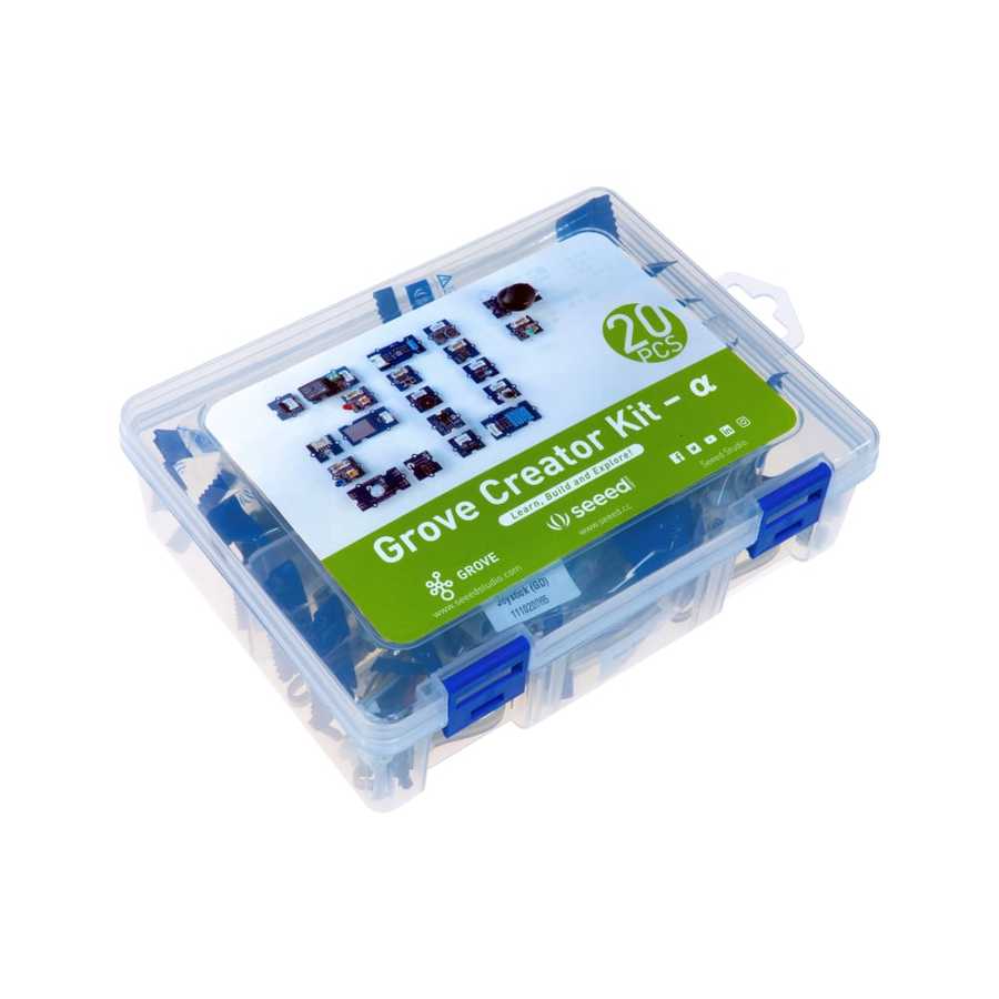
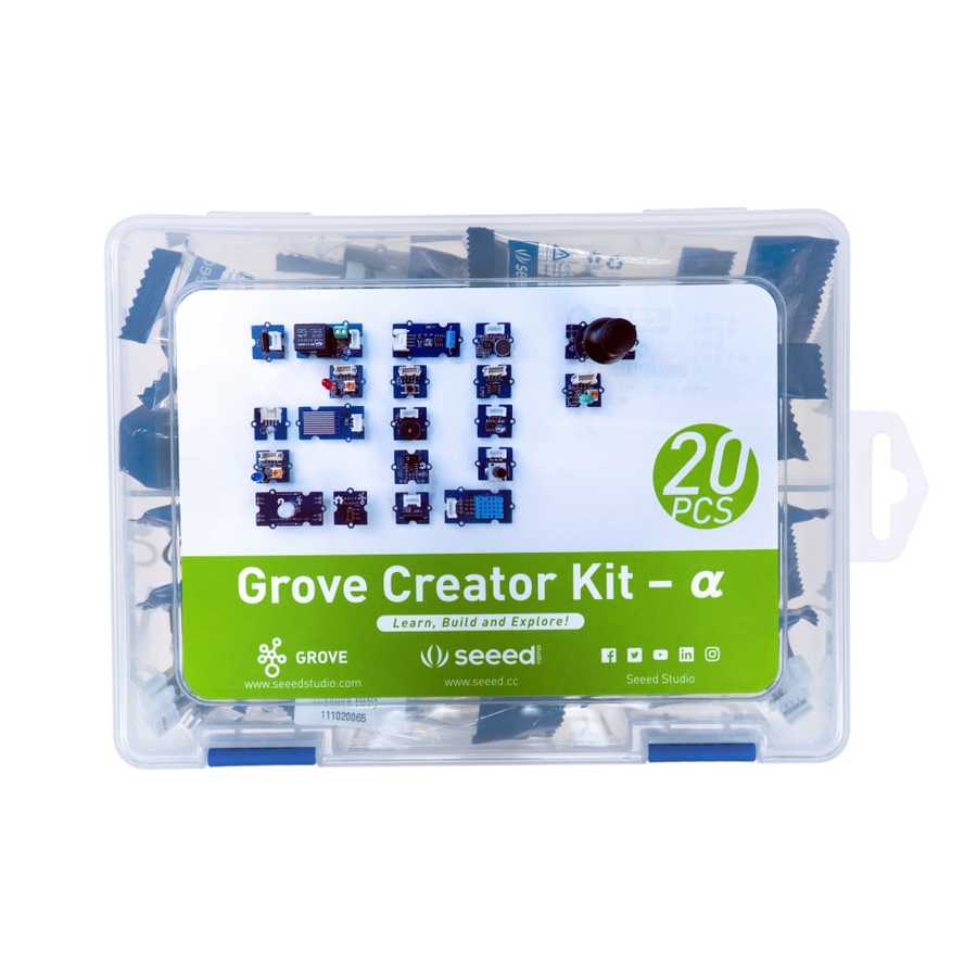
Notify me when its in stockGrove Development Kit - Alpha
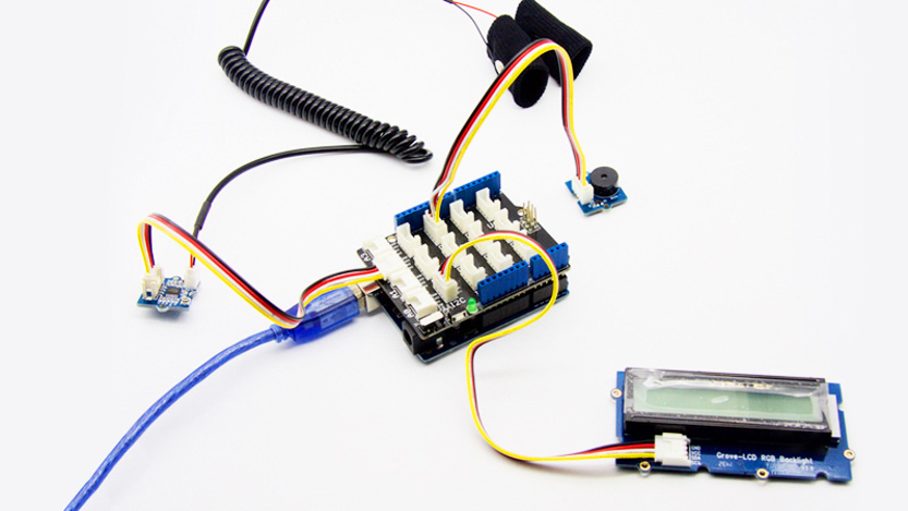
The Grove kit is an Arduino-based development set that helps you build project circuits quickly and practically. Thanks to its connector-type connections, it is an ideal set for children and beginners. Since no hand tools or extra equipment are required to build circuits, it enables very fast prototyping.
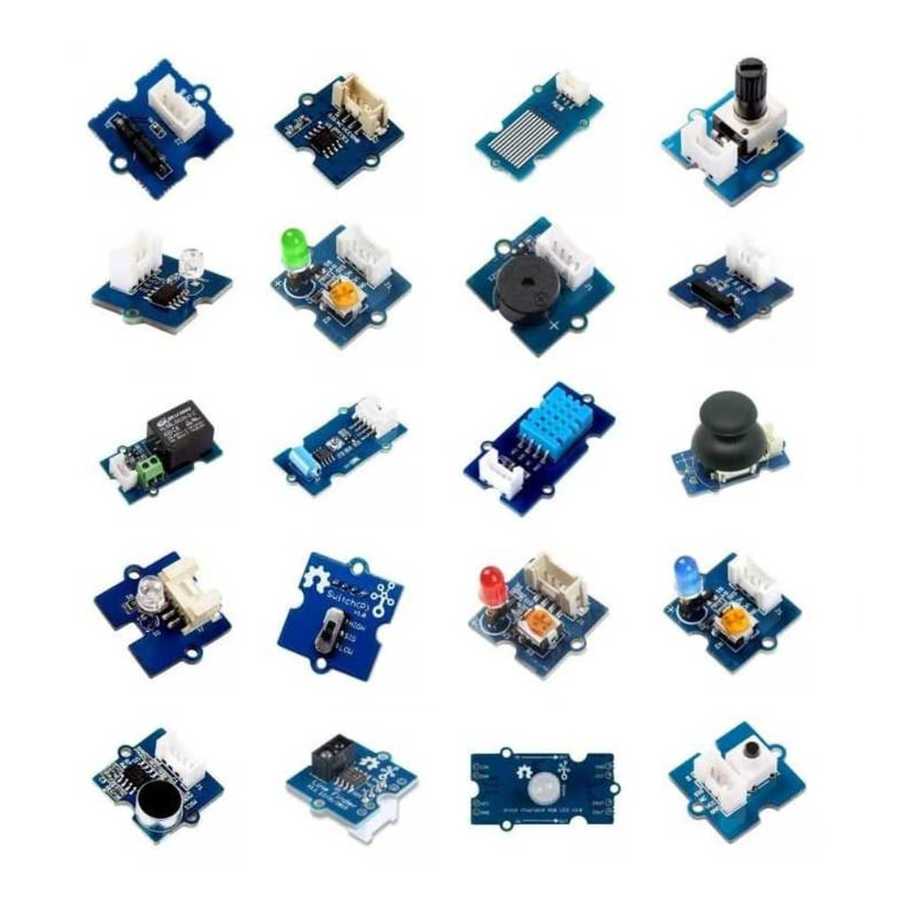
If we consider a standard Arduino circuit, even a simple LED lighting/blinking setup can take time: placing the LED on a breadboard, finding the right resistor, and connecting jumper wires. With this set, it takes only a few seconds. Choose the module for the LED color you want, plug one end of the 4-pin cable into the module and the other end into the Base Shield—done. You can quickly move on to writing code.
Grove connectors can be inserted in only one direction, preventing incorrect wiring. This helps avoid potential damage caused by wrong connections.
To use Grove modules with Arduino, the Grove Base Shield is required. This product is not included in the set, but you can purchase it separately from our website.
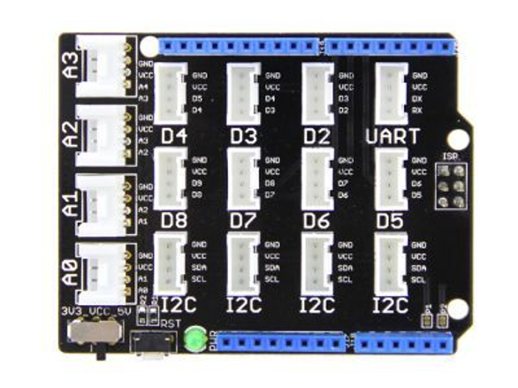
The Grove Base Shield is designed to match the Arduino R3 pin layout. Before use, please make sure you have a compatible Arduino model. It includes an onboard switch to set VCC to 3.3V or 5V, allowing compatibility with boards operating at different logic levels. To use it with older Arduino boards, you may need to solder the P1 and P2 solder jumpers on the board.
The Grove Base Shield provides Digital, I2C, Analog, and UART ports. The parts included in the set are designed to connect directly to these ports. After connecting, you can program the Arduino directly using the Arduino IDE.
In addition to the set, many modules can be purchased individually. For example, you may have the Alpha set but need a module from another set. Instead of buying the whole set, you can access other Grove products via this link and purchase only the part you need.
The connection between the module and the Grove Base Shield is made using a 4-pin cable. The function of the cable changes depending on whether it is used in Digital, Analog, UART, or I2C ports. The wire functions by color are shown in the table below.
|
Pin 1 |
Yellow |
Signal: Digital, Analog, RX on UART, or SCL on I2C |
|
Pin 2 |
White |
Signal: Digital, Analog, TX on UART, or SDA on I2C |
|
Pin 3 |
Red |
VCC |
|
Pin 4 |
Black |
GND |
Package Contents:
Recommended Products:
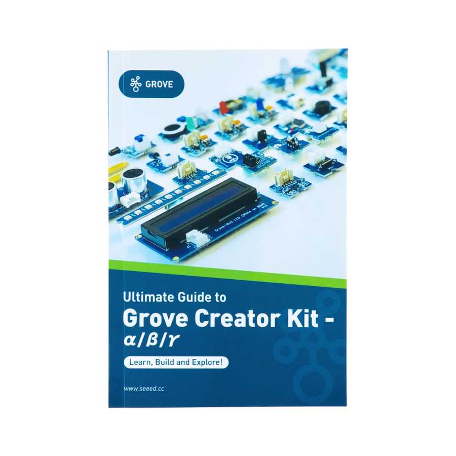
Documents / Useful Links: